If you’ve ever worked with power management, RF circuits, or low-voltage switching designs, you’ve likely crossed paths with Schottky diodes. As someone who’s spent the last 12 years supplying these components to engineers, I can say from experience that one of the most critical specs to get right for these parts is forward voltage (Vf). Mess up how you measure it, and you might end up selecting a diode that’s too inefficient for your design, or worse, fails unexpectedly under load. Schottky Diode
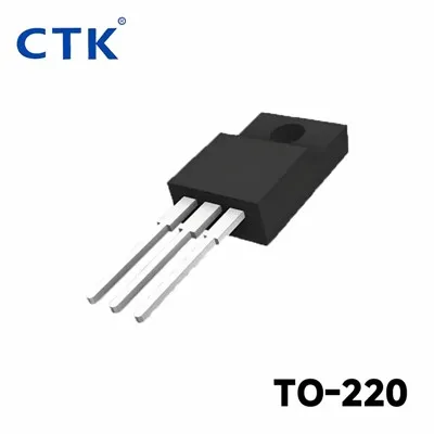
A lot of newer engineers (and even some seasoned ones) reach for a multimeter’s diode test mode when they need a quick Vf reading—but that’s not enough. Schottky diodes have a unique forward current-voltage (I-V) characteristic, different from standard PN-junction diodes, and getting an accurate measurement requires a setup tailored to their specific design. At my company, we test every batch of Schottky diodes before shipping, and our process is rooted in industry standards and decades of on-the-floor testing. Today, I want to break down exactly how we do it, so you can get reliable Vf readings for your projects too.
First, let’s get clear on what forward voltage actually is for a Schottky diode. Unlike regular diodes that use a PN junction, Schottky diodes use a metal-semiconductor junction, which is why their Vf is lower (usually between 0.2V and 0.5V, compared to 0.6V to 0.7V for silicon PN diodes). That low Vf is why they’re perfect for switching power supplies, battery chargers, and reverse-current protection—less voltage drop means less power loss. But here’s the catch: Vf isn’t a fixed number. It changes depending on the forward current flowing through the diode, the ambient temperature, and even the measurement setup. That’s why you can’t trust a random quick test.
For example, a 1A-rated Schottky diode will have a Vf of 0.32V at 1A, but if you measure it at just 1mA (what a multimeter’s diode test mode uses), you’ll get a reading of around 0.15V. That’s a huge difference, and using that 0.15V number to size your power supply could lead to overheating and efficiency losses. So step one: forget the multimeter’s diode test for critical measurements. We recommend a dedicated semiconductor parameter analyzer, but if you don’t have one, you can build a simple, accurate setup with basic lab equipment.
Let’s walk through the step-by-step process we use here, which aligns with JEDEC standards for discrete semiconductor testing. First, gather your tools. You’ll need a stable DC power supply (with precise current control, not just voltage), a precision digital multimeter (DMM) that can measure voltage to at least three decimal places, a current sense resistor (with a low tolerance—1% or better, and low temperature coefficient, because resistance changes with heat), a breadboard or test jig to hold the diode, and a current-limiting resistor (to prevent the diode from drawing too much current and burning out).
Wait, why a current sense resistor? Because we need to measure exactly how much current is flowing through the diode to correlate it with Vf. Schottky diodes follow the diode equation, but at low forward currents, the leakage doesn’t affect us—at the rated forward current, it’s all about the I-V relationship. Let’s outline the setup circuit first. It’s a series loop: positive of the DC power supply connects to one end of the current-limiting resistor, the other end of the resistor connects to the anode of your Schottky diode, the cathode of the diode connects to one end of the current sense resistor, and the other end of the current sense resistor connects back to the negative terminal of the DC power supply. That way, all components are in series, so the same current flows through every part.
Now, where do we measure voltage? Not across the entire series circuit—we need Vf, which is the voltage drop directly across the diode’s anode and cathode. So we’ll connect two voltage probes from your DMM: one to the diode’s anode terminal, and the other to its cathode terminal. That eliminates voltage drops from the current-limiting resistor and sense resistor, which would skew the reading. The sense resistor’s voltage drop is how we measure current, right? Ohm’s Law: V = I * R, so if you measure the voltage across the sense resistor, divide that by its known resistance, and you get the exact forward current (If) flowing through the diode. That’s key, because you need to pair each Vf with its corresponding If.
Next, set your test conditions. Almost all Schottky diode datasheets rate Vf at a specific forward current—usually the diode’s rated continuous forward current (IF), and sometimes at a temperature of 25°C (room temperature). Some higher-power models might list Vf at a pulsed current, but that’s mostly for transient testing. For your standard design, you want to match the test current to what the diode will actually see in operation. If you’re using a 5A Schottky in your power supply, test at 5A, not 1mA. That’s the biggest mistake we see engineers make: they test at a tiny current and then use that number for full-load calculations, leading to inaccurate results.
Once your circuit is wired correctly, it’s time to run the test. First, turn on the DC power supply and slowly increase the output until you hit your target current. Let’s say you’re testing at 1A for a 1A-rated diode: keep adjusting the power supply until the voltage across the sense resistor reads, for example, 0.1V (if your sense resistor is 0.1Ω, 0.1V / 0.1Ω = 1A). Wait a few seconds after adjusting—Schottky diodes heat up quickly when current flows through them, and as temperature rises, their Vf drops (unlike silicon PN diodes, where Vf rises with temperature). That thermal lag means you need to let the diode stabilize at the test current before taking a reading, otherwise your Vf will be off.
While you’re waiting, keep an eye on the diode’s temperature. If you’re testing at a high current (like 10A or more), the diode might get warm enough to change the reading. We recommend using a contact thermocouple attached to the diode’s package during testing, to make sure it’s at the specified 25°C. If it’s running hotter, you can either let it cool down, or adjust your test current to account for temperature—just be sure to note that in your notes, because that’s critical for comparing to datasheet specs.
Once stabilized, record two numbers: the forward current (If) from the sense resistor, and the forward voltage (Vf) directly across the diode. That’s your core reading. But wait—do you need to test only one current? No, if you want the full picture. You can take readings at multiple points: like 10% of IF, 50% of IF, 100% of IF, and even 120% of IF to see how Vf changes during transient loads. This is especially useful for designs with variable current draw, like motor drives or portable electronics that switch between high and low power.
Now, what about if you don’t have a dedicated power supply or a parameter analyzer? We get this question all the time from hobbyists and small design teams. The good news is you can build a simplified test setup, but it will have some limitations. Use a bench power supply with current limiting set to your target, a precision DMM, a low-ohm power resistor as the current limit, and two probes to measure the diode’s voltage. The tradeoff here is that you might get slightly less precise readings, especially at higher currents, but it’s still way better than a multimeter’s diode test. Just make sure you never exceed the diode’s maximum forward current—put a current limit on your power supply, and double-check that your sense resistor can handle the wattage (P = I²R, so a 1A current through a 0.1Ω resistor is 0.1W, which is standard, but at 5A that’s 2.5W, so you’ll need a higher-wattage resistor).
Another common pitfall: reverse bias during testing. Schottky diodes are sensitive to reverse voltage, so never apply a voltage higher than their reverse breakdown voltage during testing. We’ve seen new engineers accidentally hook up the diode backward, or crank the power supply too high, and destroy a batch of diodes before they even test them. Double-check your polarity: the anode is the terminal with the line or stripe marked on the diode package (usually the longer lead, but not always—check the datasheet), and that connects to the positive side of the circuit.
Wait, let’s talk about datasheet consistency, too. At my company, we test every lot of Schottky diodes using this exact process, because Vf can vary slightly between batches, even for the same model number. That’s why when you source from a reliable supplier, the datasheet is a guide, but the actual test data for your specific batch will be included (or available on request). For example, a batch of 1000 10A Schottky diodes might have an average Vf of 0.41V at 10A, with a maximum of 0.43V and a minimum of 0.39V. That’s the data you need to design with, not the generic “typical Vf of 0.4V” on the datasheet.
What about when you need to test a finished board, not just a loose diode? That’s a common scenario for engineers troubleshooting a design. To test Vf on a PCB, you can either desolder the diode (if you have space) and use the same bench setup, or test it in-circuit. In-circuit testing is trickier, though, because other components on the board (like resistors or capacitors) will affect the reading. If you test in-circuit, make sure to power off the board, disconnect any loads, and use a low-current test signal—otherwise, you might damage adjacent parts. We only recommend in-circuit testing for initial sanity checks, not for exact Vf measurements.
Let’s also clear up a myth I hear all the time: “Schottky diodes have the same Vf regardless of current.” That’s not true. Their I-V curve is exponential, just like regular diodes, but with a lower turn-on voltage. At 0.1A, a 5A Schottky might have a Vf of 0.35V, at 2A it’s 0.39V, and at 5A it’s 0.42V. That’s why matching your test current to your application is non-negotiable. If you’re designing a low-power battery charger that draws 0.5A from a 3A Schottky, testing at 0.5A will give you the accurate Vf for that operating point.
Now, after testing, what do you do with your Vf data? Use it to calculate power loss in your design. Power loss from a Schottky diode is P = Vf * If, so if your diode has a Vf of 0.4V at 5A, that’s 2W of power lost as heat. That means you need to size your heatsink accordingly, or pick a diode with a lower Vf if efficiency is critical. For applications like electric vehicles or solar inverters, that 0.1V difference in Vf can add up to hundreds of watts of lost power, so accurate measurements are a big deal.
At this point, you might be thinking, this seems like a lot of work. But it’s worth it. Too many design delays happen because engineers select a diode based on a generic datasheet Vf, only to find that at full load, it’s getting too hot or losing too much power. When you source your Schottky diodes from a supplier that provides test data per lot, and you verify that data with your own setup, you avoid those headaches.
If you’re working on a new design, or you need to test a batch of diodes for quality control, don’t cut corners. Skip the multimeter’s diode test, build that simple test circuit, and follow the steps we use in our lab here. We’ve been supplying Schottky diodes to engineers in aerospace, consumer electronics, industrial automation, and renewable energy for over a decade, and our customers rely on accurate Vf data to keep their projects on track.
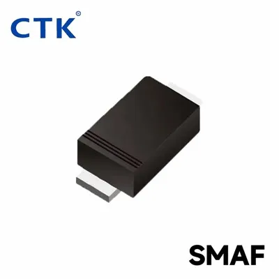
If you’re looking for high-quality, consistent Schottky diodes with full test data for every batch, or you have questions about measuring forward voltage for your specific application, reach out to our team to discuss your needs. We’re here to help you select the right parts and ensure your testing process is accurate and efficient.
Fast Recovery Diode References
- JEDEC Standard No. 28-A, Definitions of Semiconductor Diode Parameters, 2019.
- International Rectifier, "Schottky Diode Application Note: Forward Voltage Testing and Characteristics", 2021.
- Diode Equations for Semiconductors, Physics Today, 2018.
Tongke Electronic Co., Ltd
Tongke Electronic Co., Ltd. is one of the most experienced schottky diode manufacturers and suppliers in China, featured by quality products and low price. Please rest assured to wholesale advanced schottky diode made in China here from our factory. Contact us for pricelist.
Address: No.3,Chayuan Rd, Street 3, AilingKan, Dalingshan, Dongguan, Guangdong, China.
E-mail: jack@ctk-elec.com
WebSite: https://www.ctkchip.com/
