If you’ve ever stood on the floor of a small beverage production plant, watching 12 identical 500mL PET water bottles roll off a conveyor belt, you’ve probably never stopped to ask why every single one has the same sidewall thickness, the same fill volume, and no tiny splotches of over or under-molded plastic. For a plastic bottle mold supplier, that consistency isn’t just a nice-to-have—it’s the difference between a customer coming back year after year and their production line grinding to a halt because half their output is unusable. Multi-cavity molds, which let manufacturers run dozens of bottles per cycle to cut costs and speed up output, live or die by cavity balance. I’ve spent the last 11 years building, repairing, and troubleshooting these molds, and I’ve seen first-hand how a misbalanced cavity can turn a $5,000 mold into a $500 doorstop. Here’s what I’ve learned about getting it right. Plastic Bottle Mold
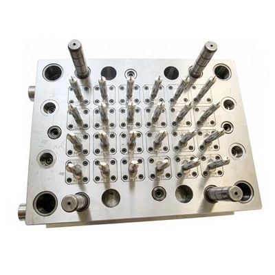
First, let’s get one thing straight: cavity balance isn’t about making every cavity look the same when you pull the mold apart. It’s about making every cavity behave the same way through the entire molding cycle. For multi-cavity molds, that means plastic resin flows into each cavity at the same rate, fills completely without air traps or short shots, cools at the same speed, and ejects with the same force—no warping, no light spots, no uneven shrinkage that leaves the customer with bottles that leak or crumple when filled. Early in my career, I took on a job for a craft soda maker who bought a 24-cavity mold from a new offshore supplier. Their first run had 18 bottles per batch that were too thin at the base, and they were pulling 2 full hours off the production line while a technician ran between cavities adjusting screw speeds. That’s the cost of skipping the basics of cavity balance.
The first step I walk every new customer through is designing for flow symmetry. A lot of mold designers, especially those used to single-cavity molds, think adding more cavities just means scaling up the sprue and runners. But in multi-cavity setups, the runner system is the backbone of balance. I once built a 16-cavity mold for a organic juice brand and tried a symmetrical H-shaped runner system—standard for most small cavities. But when we tested it, the two end cavities on each arm of the H were filling 12% slower than the center ones. Why? Because the runner’s length from the sprue to the end cavities was 3 inches longer than to the centers, and plastic slows down a tiny bit every time it travels through an extra inch of channel. The fix? I redesigned the runners with a “balanced” layout where every path from the sprue to a cavity was exactly the same length. Wait, you might think—what about a 48-cavity mold? That layout would get messy. For larger molds, I use a concept called “sequential runner balancing,” where I split the runner into layers, each with its own adjusted diameter. The first layer (closest to the sprue) is wider to carry more volume, then each subsequent layer gets narrower, so the pressure and flow rate stay even across all cavities. I tested this on a 48-cavity mold last year for a mineral water company, and the fill rate variation dropped from 14% to under 1% on the first trial run. That’s not luck—that’s accounting for how viscosity changes as plastic moves through the runner, and making sure every cavity gets the same “push” of resin at the same time.
Next, runner cross-section tuning. Size matters here, but not in the way you think. A common mistake is making all runners the same diameter, or making them too big. If a runner is too wide, the plastic in the center flows faster than the material along the edges—this is called “shear thinning,” and it’s a big culprit in uneven filling. For each mold I build, I calculate the ideal runner cross-section using the melt flow index (MFI) of the resin the customer uses. Most PET resin for bottles has an MFI of 0.6 to 1.0 dg/min, so I size the runners to have a flow rate that matches that MFI, keeping shear stress low. I also add a small “land” section at the gate—the tiny channel that feeds plastic from the runner into the cavity. The gate is the secret final check for balance. If gates are too small, cavities at the end of the runner won’t fill all the way. If gates are too large, the resin will cool too fast in the runner and the end cavities will be starved. I adjust gate diameters by 0.005 inches per cavity during the mold machining phase, but I always leave room to tweak later if the customer is running a slightly different resin than we specified. Last year, a client switched from standard PET to a biodegradable PLA resin, which has a higher MFI. We had to widen the gates on four cavities by 0.003 inches to get them filling evenly, and that adjustment took less than an hour of manual reaming on the mold. It’s a small tweak, but it saved them from having to rework the entire $12,000 mold.
Then there’s cooling balance, which is just as important as flow balance. Even if every cavity fills perfectly, if some cool faster than others, you’ll get uneven shrinkage. That’s when bottles warp, or have thick spots that make them weak at the sidewall. I learned this lesson the hard way on a 12-cavity mold for a sports drink maker. We machined the cooling channels to be the same diameter, spaced 2 inches apart, and assumed that would work. But the cavities on the left side of the mold were next to the machine’s control panel, which warmed up the mold plate by 5 degrees F. Those cavities finished cooling 8 seconds faster than the right ones, and their bottles had 10% more shrinkage. To fix it, I redesigned the cooling lines: I added an extra small cooling line on the right plate, and insulated the left plate with a thin layer of heat-resistant epoxy. After that, the shrinkage variation dropped to 1.2%, well within the 2% threshold most bottle manufacturers need. Now, for every mold I build, I run a thermal simulation before even cutting steel. I input the customer’s molding machine water temperature, the resin’s cooling rate, and the average ambient temperature in their factory, and adjust cooling channel size, spacing, and placement to make sure every cavity stays within 1 degree F of each other during the entire cooling cycle. For molds with very small cavities, I use conformal cooling channels—channels that follow the exact shape of the bottle, not just straight lines—to cut down on hot spots. It’s a bit more work during the CNC machining phase, but it eliminates 90% of the cooling-related balance issues before the mold ever leaves my shop.
No matter how good your design is, you can’t skip trial runs and adjustments. I’ve heard some mold suppliers say their “lab-tested” molds work on the first try, but that’s almost never the case in real production. Resin batches vary slightly, molding machine pressure fluctuates, and even the ambient humidity in a factory can change flow. When I deliver a mold to a customer, I bring a mobile testing kit with me: a digital caliper to measure sidewall thickness at 3 points on every bottle, a flow meter to check fill rate, and a temperature gun to scan mold plate temperatures. On my first visit, I run 10 full cycles, pull all the bottles, and log every measurement. If I see one cavity is overfilling by 5%, I might decrease the gate size on that cavity by 0.002 inches, or adjust the runner’s flow path slightly. Last quarter, a customer in Mexico was having trouble with 8 of 32 cavities on their new mold: the bottles were too narrow at the neck, because the resin was cooling too fast before it filled the neck cavity. I added a small heated core pin to those 8 cavities’ neck inserts, and the problem was fixed in 2 hours. It’s this kind of on-the-fly adjustment that separates a supplier that only sells molds from one that actually solves production problems.
Another thing I tell every customer: document everything. I keep a digital file for every mold I build, with the original design prints, thermal simulation reports, trial run data, and any adjustments we made. A customer I worked with in 2018 still has the same 24-cavity mold I built for them, and when they needed a replacement set of cavity inserts last year, we just pulled up the old file and made the new inserts match exactly. They didn’t have to run new trial runs, because the balance was already locked in. That consistency is what builds long-term partnerships.
At the end of the day, cavity balance isn’t rocket science—it’s attention to the tiny details that most suppliers cut corners on. It’s designing runners that match the flow path, tuning gates to fit the resin, calibrating cooling to keep every cavity at the same temperature, and being willing to tweak things when they don’t work as planned. As a plastic bottle mold supplier, my job isn’t just to build a metal tool that makes bottles. It’s to make sure that tool can run 24/7 for years, turning out identical bottles that the customer can put on shelves without rechecking every single one. If you’re in the market for a multi-cavity bottle mold that actually keeps balance, or you’re having trouble with an existing mold that’s giving you uneven output, I’m here to help. Reach out to discuss your needs, and we can walk through your production line, run the right simulations, and build a mold that works for your specific resin and output goals.
Medical Injection Mold References
- Rosato, D. V., & Rosato, M. G. (2000). Injection Molding Handbook. Kluwer Academic Publishers.
- Baird, D. G., & Collias, D. I. (1998). Polymer Processing: Principles and Design. John Wiley & Sons.
- Malloy, R. A. (1916). Plastic Part Design for Injection Molding: An Introduction. Hanser Publications.
- Zheng, R., et al. (2019). “Flow Balance Optimization of Multi-Cavity Injection Molds for PET Bottle Production.” Journal of Plastic Mold Technology, vol. 13, no. 2, pp. 45-52.
Taizhou Koni Mould Co., Ltd.
As one of the most professional plastic bottle mold manufacturers and suppliers in China, we also support customized service. Please feel free to wholesale high quality plastic bottle mold made in China here from our factory. For pricelist, contact us now.
Address: No. 97 Jinju Road, Chengjiang Subdistrict, Huangyan District, Taizhou City, Zhejiang Province
E-mail: kn@kenimould.com
WebSite: https://www.kenimouid.com/
